Back to Knowledge Hub
3 min read Published by Stelsen Technical Services · Reference: NFPA 72 Chapter 14 (Inspection, Testing & Maintenance)

NFPA 72 Fire Alarm Testing Frequencies: How Often Fire Alarms Should Be Tested

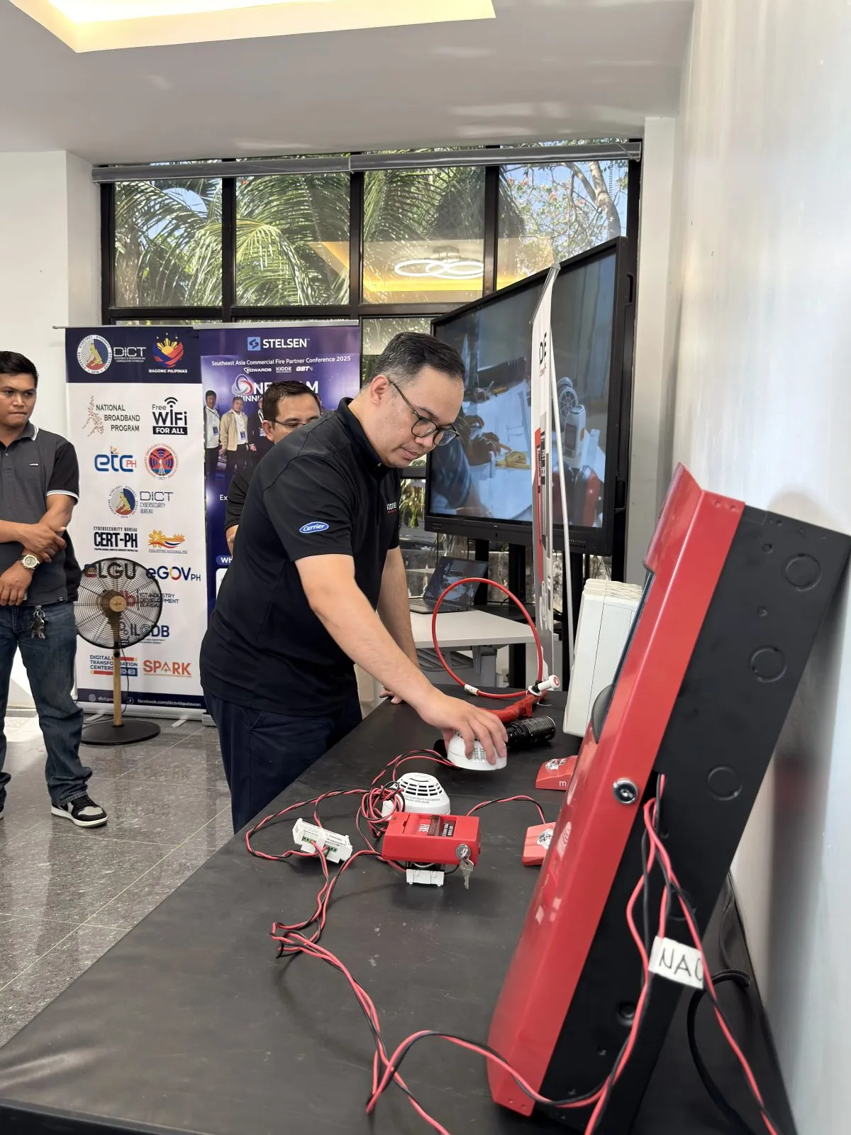
Stelsen engineer testing fire alarm detectors and devices
Stelsen Engineering Infrastructure & Fire Safety Compliance Advisory

A fire alarm system only protects a building if every device still works on the day it is needed. NFPA 72 covers that through Inspection, Testing, and Maintenance (ITM) — a fixed schedule of checks rather than an occasional walk-through. The intervals below are the baseline schedule applied to commercial buildings.

Confirm every interval against the NFPA 72 edition adopted by your Authority Having Jurisdiction, the equipment manufacturer's published requirements, and the RA 9514 / BFP conditions attached to your occupancy. Where these differ, the strictest requirement governs.

Inspection, testing, and maintenance are three separate duties

Inspection is a visual check that devices are in place, unobstructed, undamaged, and free of anything that would block smoke or sound. Testing is a functional check that a device actually delivers the correct signal to the panel. Maintenance is the corrective work that follows — cleaning, recalibration, or replacement. Passing a visual inspection never substitutes for a functional test.

Monthly: control panel and power supply

Confirm the fire alarm control panel sits in normal condition with no unresolved alarm, trouble, or supervisory signals, primary power present, and the standby battery set free of corrosion, swelling, or leaking terminals. Vented and non-sealed battery types, and engine-driven emergency power, need this look every month. Sites with a constantly attended location or full off-premises monitoring may inspect the panel less often — check which case applies to your building.

Quarterly: duct detectors, waterflow, and supervisory devices

Duct smoke detectors, waterflow switches, valve tamper and other supervisory switches, and off-premises signal transmission equipment are commonly placed on a quarterly cycle. Many facilities align these with sprinkler system ITM under NFPA 25 so one service visit covers both trades.

Semi-annual: initiating devices and interfaces

Manual pull stations, heat detectors, notification appliances, sealed lead-acid batteries, and system interfaces to elevator recall, HVAC shutdown, door holders, and fire doors are inspected at least twice a year. These interfaces fail quietly — the panel can report normal while a linked function no longer operates.

Annual: full functional testing

Once a year the system is exercised end to end: 100% of initiating devices tested (smoke detectors, heat detectors, manual stations, monitor and control modules), notification appliances confirmed for audibility and visibility in every occupied area, battery load and discharge testing, emergency voice communication checked, ancillary functions verified, and signal receipt confirmed with the monitoring station. This is the test that supports your inspection certificate.

Smoke detector sensitivity testing

Sensitivity is separate from functional testing. Smoke detectors are sensitivity tested within the first year after installation, then on the alternate-year cycle afterward. Where the panel monitors detector sensitivity automatically and reports devices drifting out of their listed range, a documented record of in-range readings can extend that interval — the panel report becomes the evidence.

Documentation the BFP will ask for

Keep the record of completion from installation, an ITM report for every service visit, the running list of deficiencies with corrective action and retest dates, a current device inventory reflecting every renovation, and monitoring station records. Store a copy at the panel — inspectors ask for it there, and missing paperwork delays FSIC renewal more often than failed devices do.

What usually turns up during annual testing

The recurring findings are zones left disabled after maintenance and never restored, detectors past their sensitivity window, devices painted over or blocked by newly installed ceiling work, strobes obstructed by partitions added during fit-outs, batteries beyond service life, and devices added during renovation that were never programmed into the panel or added to the as-built records.

4 min read Published by Stelsen Technical Services · Reference: NFPA 72 System Architecture

Choosing Between Conventional and Addressable Fire Alarm Systems

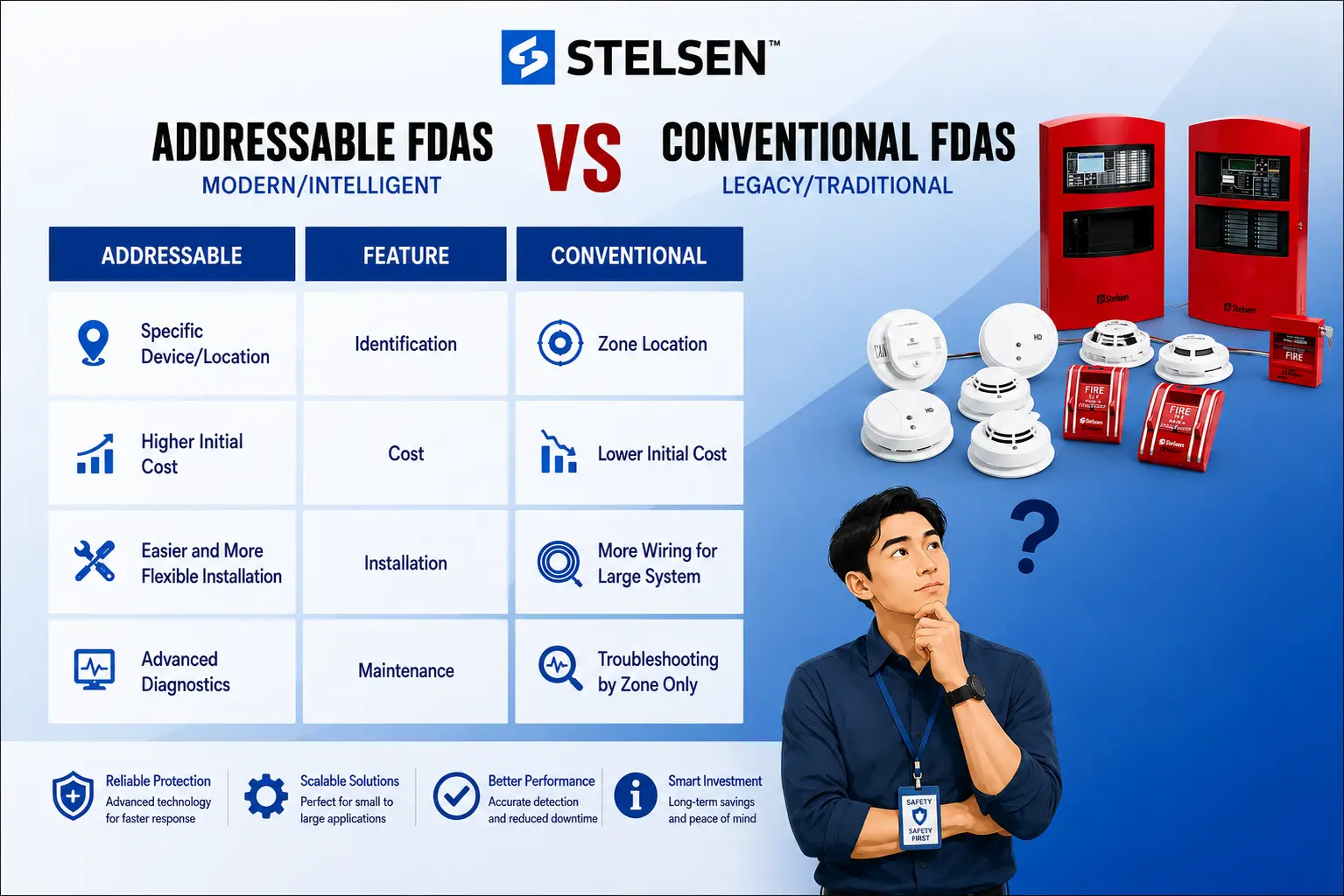
Stelsen comparison of addressable and conventional fire alarm systems across identification, cost, installation, and maintenance
Stelsen Engineering Infrastructure & Fire Safety Compliance Advisory

The choice between conventional and addressable is not about which technology is better — it is about how precisely the panel needs to tell you where the problem is, and how much the building will change over the next fifteen years. Both are listed, code-compliant architectures. The difference shows up in wiring, in response time during an actual event, and in how easily the system absorbs change later on. The table below sets the main points side by side.

Side-by-side comparison
Consideration Conventional Addressable
Fault and alarm reporting By zone — the area is identified, not the device By device — exact location and device type
Field wiring Home-run circuit per zone back to the panel Shared loop serving many devices
Hardware cost Lower panel and device cost Higher panel and device cost
Adding devices later New home-run; panel swap once zones run out Tap the existing loop up to its rated capacity
Annual ITM effort Manual records; separate sensitivity instrument Panel logs and reports (analog addressable)
Replacement parts Largely interchangeable across brands Proprietary to the panel manufacturer
Best suited to Small, fixed-layout facilities Large, changing, or multi-storey buildings

How each architecture reports a fire

A conventional system wires devices into zones. When any device on a zone activates, the panel lights that zone — "Zone 3, second floor east." Someone still has to walk the zone to find which detector operated. An addressable system gives every device its own address on a signaling line circuit, so the panel reports the exact device: "Smoke detector 042, second floor east corridor, near stair 2." That difference is minutes of search time during the one event where minutes matter.

Wiring and installation cost

Conventional systems need a separate circuit home-run to the panel for every zone, so cable quantity climbs quickly as zones multiply. Addressable systems put many devices on a single loop, which usually means less cable and fewer panel terminations in a mid-size or larger building. Panel and device unit costs run higher for addressable, so on small sites the conventional total often lands lower — the crossover point depends on device count and building geometry, not on floor area alone.

Where conventional still fits

Small warehouses, single-storey commercial units, small offices, and standalone facilities with a modest device count and simple layout are well served by conventional systems. If maintenance staff know the zone layout and a zone covers a space that can be checked in under a minute, the extra precision of addressable buys little. Budget-constrained retrofits in buildings with an unchanged floor plan are the other common case.

Where addressable earns its cost

High-rise towers, hospitals, hotels, malls, schools, and campuses need device-level identification — in these buildings a zone can span an entire floor, and searching it during an alarm is not acceptable. Addressable panels also supervise each device individually, so a missing or failed device is reported as a specific fault instead of a general trouble signal on a zone.

Addressable is not automatically analog addressable

This distinction gets skipped in most sales conversations. A plain addressable device reports its identity and its state — normal or alarm. An analog addressable device also reports a measured value back to the panel, which is what allows drift compensation, dirty-detector warnings, and sensitivity readings pulled from the panel instead of from a test instrument. Most of the maintenance advantages described below depend on analog addressable devices specifically, so confirm which one a quotation actually covers.

Hybrid systems: the usual retrofit answer

The choice is rarely all or nothing. An addressable panel can accept existing conventional devices through zone interface modules, so a building can keep its installed detectors and field wiring while the panel, new floors, or renovated areas move to addressable. This is the common path for older buildings where full rewiring is impractical, and it lets a property upgrade in phases as budget allows. The trade-off is that the retained conventional sections still report at zone level only — the precision applies to the addressable portion.

System selection has to be confirmed against the occupancy classification and requirements imposed by the BFP for your project under RA 9514, alongside the design documents reviewed by your fire protection engineer. Device counts, loop capacities, and survivability requirements decide the final architecture.

A practical way to decide

Count the devices in the design and ask how long it would take a responder to walk the largest single zone. If that answer is uncomfortable, or if the floor plan is expected to change, specify addressable. If the site is small, the layout is fixed, and every zone can be cleared at a glance, conventional remains a sound and fully compliant choice.

3 min read Published by Stelsen Technical Services · Reference: NFPA 72 (nuisance alarm guidance)

Common Causes of False Fire Alarms in Facilities and Prevention Protocols

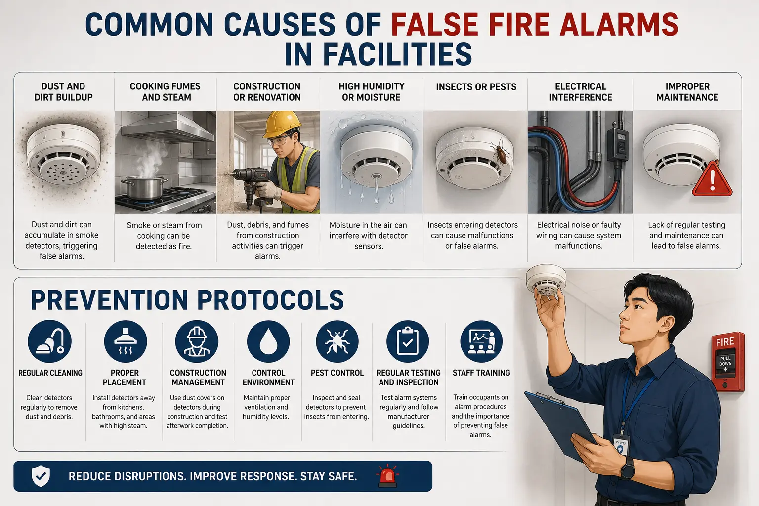
Common causes of false fire alarms in facilities and the matching prevention protocols
Stelsen Engineering Infrastructure & Fire Safety Compliance Advisory

Every false alarm costs something: an evacuation that stops trading or production, a fire service response, and — the expensive one — a building population that starts treating the next alarm as another nuisance. Most false alarms are not equipment defects. They are detectors doing exactly what they were designed to do, installed in a place or a condition that was never right for them.

Seven causes behind most facility false alarms

Dust and dirt buildup is the leading cause. Particles accumulating inside the sensing chamber scatter light the same way smoke does, so the detector reports what it sees. Cooking fumes and steam from pantries and canteens read as combustion products to a photoelectric sensor. Construction or renovation releases concrete dust, sawdust, and fumes — drilling one ceiling anchor near an unprotected detector is enough. High humidity or moisture condenses inside the chamber, and water droplets scatter light like smoke particles. Insects crawl into chambers seeking warmth and darkness, blocking or triggering the optical path. Electrical interference from faulty wiring, poor grounding, or nearby equipment produces spurious signals on the circuit. Deferred maintenance ties them all together: a detector never cleaned or tested will eventually fail in the direction of a false alarm.

Placement is the root cause more often than the device

Before replacing a detector that keeps activating, check what is around it. Detectors within a few metres of kitchen exhaust, near supply air diffusers, at loading bays open to vehicle exhaust, in unconditioned parking levels, or beside shower and laundry rooms are working in conditions that a standard photoelectric smoke detector was not selected for. The fix is usually relocation or a change of device type — heat detectors in kitchens and parking areas, multi-criteria or dust-tolerant detectors where particulates are unavoidable — not another replacement of the same model in the same spot.

Never leave a zone disabled or a detector covered as a shortcut around recurring false alarms. The building is unprotected for as long as the bypass stays in place, and responsibility for it sits with the building owner or administrator under RA 9514.

Prevention protocols that actually reduce the count

Clean detectors on the maintenance schedule rather than after complaints. Place and select devices for the actual room conditions, not for a uniform ceiling layout. Manage construction dust with covers and daily restoration. Keep humidity and ventilation within the equipment's listed range. Seal entry paths and include detector heads in the pest control programme. Test and inspect on the published interval, following manufacturer guidance for cleaning method and service life. Train occupants and staff on what to do during an alarm, so a real event is never met with the assumption that it is another nuisance.

3 min read Published by Stelsen Technical Services · Reference: ANSI/TIA-568 Series

Structured Cabling Standards: What ANSI/TIA-568 Requires for Commercial Buildings

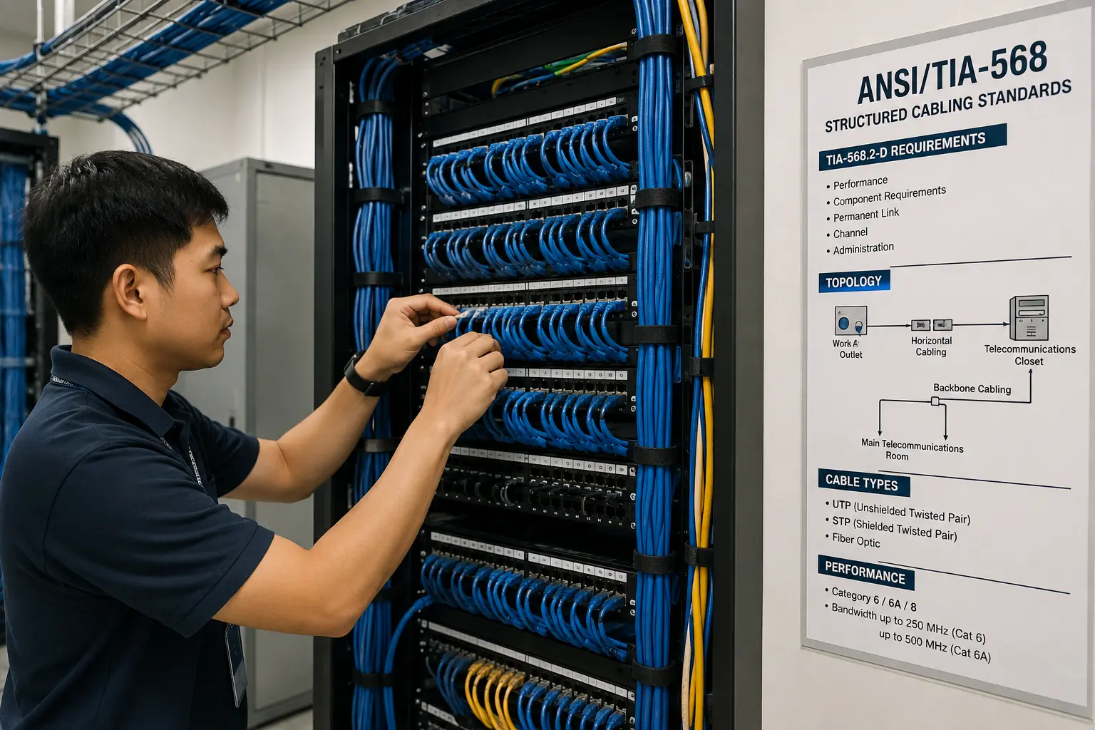
ANSI/TIA-568 structured cabling standards: a technician terminating patch panels in a server rack, alongside the TIA-568.2-D requirements (performance, component requirements, permanent link, channel, administration), the work area to telecommunications closet topology, cable types (UTP, STP, fibre optic), and Category 6/6A/8 performance specifications

Structured cabling is a standardised, hierarchical wiring system rather than a point-to-point run pulled wherever a device happens to sit. Built to ANSI/TIA-568, it lets any outlet be reassigned to voice, data, or a security device without re-cabling the floor, and it is what keeps a building's network serviceable ten years after the original design drawings are gone.

The standard architecture: entrance to work area

ANSI/TIA-568 defines the system as a chain of defined spaces: the entrance facility where outside cabling enters the building, the equipment room housing core switching and servers, telecommunications rooms on each floor, backbone cabling connecting those rooms vertically, horizontal cabling running from the telecommunications room to each work area, and the work area outlet itself. Every run has a defined start and end point in this chain — nothing is spliced or daisy-chained between spaces.

Choosing a cable category

Category 6A supports 10GBASE-T at the full 100-metre channel length and is the practical minimum for a new commercial installation. Category 6 supports 10GBASE-T only at reduced distance, and Category 5e is no longer specified for new work. Fibre — multimode for shorter high-bandwidth backbone runs, single-mode for longer or campus-scale runs — takes over where copper's distance or bandwidth limit is reached.

The 100-metre channel limit

Copper horizontal cabling is limited to a 100-metre channel: 90 metres of permanent link between the telecommunications room and the outlet, plus up to 10 metres of patch cords combined at both ends. Exceed it and performance degrades in ways a passing continuity check will not reveal — the run needs to be shortened or the telecommunications room relocated, not patched around.

Certification testing, not a continuity check

A tone-and-probe or continuity tester confirms the wires are connected, nothing more. Certification against ANSI/TIA-568 is a separate step, run with a calibrated field tester that measures wiremap, length, insertion loss, and near-end crosstalk, among other parameters. It is run two ways: a permanent link test covering the fixed cabling from patch panel to outlet, and a channel test that includes the patch cords and models the path as it will actually be used. A signed certification report per run is the evidence the installation meets spec — a passing continuity test is not.

Cabling and unshielded power conductors run in parallel need separation to avoid electromagnetic interference on the data circuit. ANSI/TIA-569 sets the pathway and separation requirements — follow the edition your project specification references rather than a rule of thumb.

Labelling carries the system after handover

ANSI/TIA-606 governs administration: every cable, patch panel port, and outlet gets a unique identifier that is cross-referenced in a cable schedule. A cabling plant that passed certification but was never labelled to this standard still costs the next technician hours tracing a single run — the documentation is what makes the certification usable later, not just at handover.

3 min read Published by Stelsen Technical Services · Reference: ASHRAE Guideline 0 / BCxA Practice

What a Complete Building Systems Turnover Package Should Include

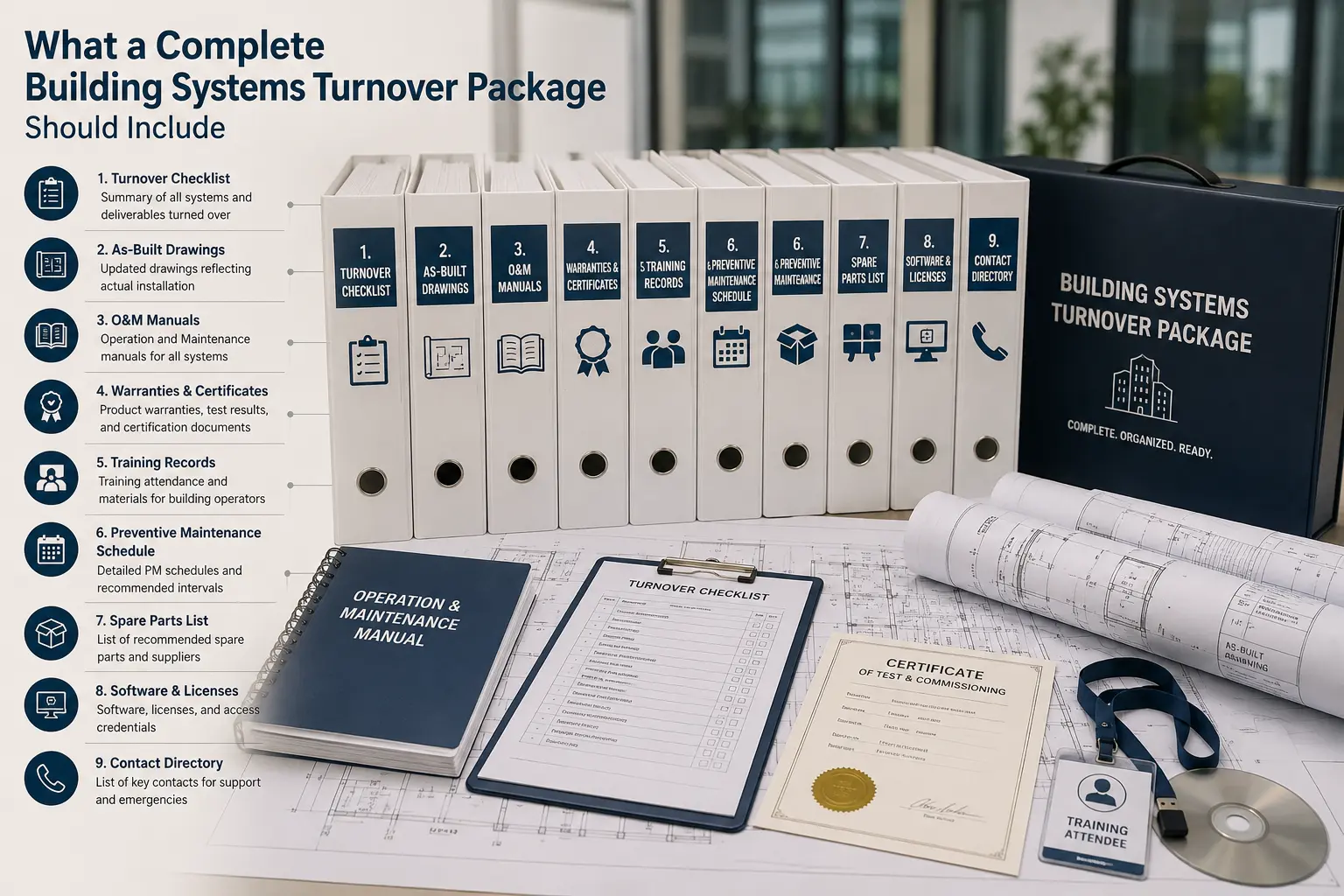
What a complete building systems turnover package should include: turnover checklist, as-built drawings, O&M manuals, warranties and certificates, training records, preventive maintenance schedule, spare parts list, software and licenses, and contact directory, packaged as labelled binders alongside the turnover checklist, O&M manual, and certificate of test and commissioning

Turnover is the point where responsibility for a system passes from the installer to the owner or operator. A rushed one does not show up as a problem on handover day — it shows up eighteen months later, as an unexplained fault with no as-built to check against, or a warranty claim that gets declined because the required service interval was never documented.

As-built documentation, not the design set

Design drawings show intent; as-builts show what was actually installed — device locations, wiring routes, panel and zone schedules, updated to match every field change made during construction. This is the single most common gap in a weak turnover, and the one that costs the most later: without it, every fault investigation starts by re-discovering the building instead of consulting a record of it.

Operation and maintenance manuals

A complete O&M package includes manufacturer data sheets for every installed model, the panel's programming record — device addresses, zone assignments, cause-and-effect matrix, access credentials — the documented sequence of operations, and a current backup of the panel configuration. Generic manufacturer literature is not a substitute for the as-configured record of this specific installation.

Testing and acceptance records

Functional test reports for every system, the applicable Authority Having Jurisdiction's acceptance sign-off, and a closed punch list showing every deficiency found during commissioning was corrected and re-verified — not just logged. An open punch list item at turnover is a known defect the owner is now responsible for, whether or not anyone tells them so.

Hands-on training for facility staff

A manual handed to someone who has never operated the system is not training. The people who will run it day to day need a walkthrough on-site — acknowledging, silencing, and resetting a fire alarm panel and reading its event log, or knowing the patch panel layout and cross-connect records for a structured cabling plant — before the installer's team leaves.

Note the applicable warranty period and the service intervals required to keep it valid, and confirm what spare parts — batteries, common detector types, patch cords — should be stocked on-site so a routine failure does not wait on a supply order.

Turnover starts the maintenance clock

The date a system passes to the owner is the date equipment starts ageing against its warranty and the first preventive maintenance interval starts counting. On larger or more complex projects this handover is run as a formal commissioning process, with independent verification that systems perform as designed, following a framework such as ASHRAE Guideline 0 or the practices published by the Building Commissioning Association (BCxA). Most single-building fire and security turnovers use a lighter version of the same checklist without a dedicated commissioning agent — the documents above are what that checklist actually verifies.